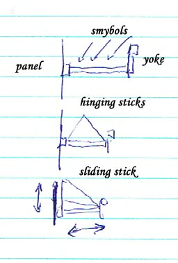
Yoke Elevator position indication methods. Fig above shows 3 means by which the
elevator angle produced by the yoke position can be viewable by the pilot while
flying. Not shown is the use of a flexible push pull cable which would be very
versatile in showing elevator position in all control systems.
This elevator angle can be correlated to the long term angle of attack that it
causes the main wing to assume under power. Depending on the model of aircraft
there may be a variation on the angle of attack that the elevator causes when
power is applied and flaps deployed. With power and flaps the aircraft will stall
at a more forward or less back position of the control than it would stall in
a flapless power off glide. On some swept or delta wing aircraft which are unstable
the relation between elevator position and wing angle of attack may not hold true.
Labeling and coloration of the elevator position indicator must accommodate and
inform of these differences. If the accommodation is too difficult a single important
condition could be labeled, go-around climb transition and or engine failure glide.
An Ideal aircraft would not have different elevator angle to main wing angle of
attack with changes in thrust.
Today's Digital Computer Autopilots mimic existing human training conventions,
where the controller chases the sensor input in a feedback loop. Generally the
feed back look is trying to establish a desired pitot tube determined airspeed.
In this invention the desired airspeed is obtained by placing the power and tailplane
controls in predetermined positions to cause the desired flight condition or speed
even if there is no pitot tube to measure the speed. A predetermanitive controls
system instead of a reactive control system. There have been many crashes of manned
and unmanned aircraft where the pitot tube airspeed system has been blocked by
ice , and thusly the feedback loop control system in the pilots head or in the
computer has mindlessly dove the aircraft into the ground or dove to an excessive
structural breakup airspeed despite the elevator position and engine power being
in positions which would inevitably and obviously result in excessive airspeed
or impact with the ground. First you have to actually keep track of or command
specific elevator angles and power settings, than a predetermanitive control system
may be able to fly an aircraft with no feed back loop instruments at all. Engine
power and tail plane movable surface angles relative to the aircrafts main wing
form the primary Table lookup values that determine flight condition. Full
view of Tabular Flight Control Data .
Thus in a condition of complete human display instrument or ground link failure
or computer control failure, an aircraft could control itself in a primitive way
until the situation could be rectified.. Whether manual human control, or analog
mechanical or electric computer or digital computer memory. Critics my fault the
loss of exactitude of such a system to respond to other variables. Detailed control
could be bracketed around the traditional airspeed feedback loop to prevent gross
logical error. This is shown in the images of the wide spreadsheet format of tabular
data. Alarms could be raised or limits imposed on the feedback control system
by the tabular desired flight condition value limits of reasonableness. Two aircraft
control surfaces systems could co- exist: The Table look up major control setting
system which requires low bandwidth communications or computation and the limited
control system joystick or feedback loop detailed control system with requires
high bandwidth communication or computation, thus the feedback system would be
mechanically limited.
For existing manned General Aviation aircraft, Predictive Table Lookup controls
with shaped and colored symbols that represent desired standard operating flight
conditions can be used.