Placement viewed from the front 
Side View of the target and tell tale
strut 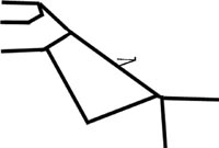
View from the pilots view 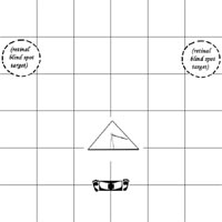
Detail Target 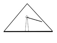
g. 5. Windscreen System, front view. The Perspective Grid pattern of very fine
line markings is well known as having been used by Dutch Painters as a tool for
perceiving the spot of converging vanishing point perspective. The painters would
construct the grid out of wire in a frame and place it on a stand some distance
in front to assist in perception of converging depth. It is difficult to look
only for the spot of convergence, it is more easily located by seeing the larger
distortions around the convergence and pointing to it. This point of convergence
is important in landing an aircraft because the aircraft is moving, and the point
of convergence that is not moving in the windscreen is the point where the airplane
is likely to impact the ground. The grid would make it easier and more obvious
to perceive this point of convergence continuously and accurately during the landing
approach. There is also a technique of a constant angle with the horizon by seeing
and constant distance on the windscreen with the horizon. The grid should help
in these perceptions, although the detection of the vanishing point is believed
to be the better method.
[Para 22] Fig. 6. Windscreen System, side view. This view shows the protruding
holder for the target, and angle of attack and yaw vane. It is hoped that by testing
and method it can be possible to calibrate the vane despite the variations in
propeller slipstream problems in a single engine tractor aircraft. A very spiky
or furry stick or yarn could have damping and Reynolds number effects which would
limit vibration. The vibration and lack of exactitude that could result from placement
in the propeller slipstream could have some benefit in solving one of the problems
of simple angle of attack flying. When a pilot closely chases or targets a specific
angle of attack he can cause a phugoid oscillation of the whole aircraft where
it cyclically changes airspeed at the same angle of attack. Since this condition
is prevalent some accommodation has to be made, in the pilots head or in the instrument.
The pilot can use the angle of attack information as a gross guide to see where
he is trending, and look at the airspeed and the pitch angle to dampen the oscillation.
If the angle of attack and yaw vane in this application is vibrating about then
it can only be used for gross interpretation and not for fine chasing so the two
problems cancel each other a bit. The benefit is still there since accidents typically
involve gross errors that begin some time before the accident occurs. Since the
subject instrument is right in front of his face out of the window in the direction
he is going then gross errors could be seen before they become irrecoverable.
This type of instrument could still have utility and improved accuracy if placed
in some location outside of the propeller where the pilot can get a decent look
at it. A pith ball tube type windspeed indicator can be placed in concert with
the angle of attack indicator. This is a clear tube with many holes drilled all
along it and capped at the top, the air from below blows the ball upward. It is
inexpensive but it requires calibration to the expected pitch angle of the plane
since it is gravity dependant. Spring loaded airspeed indicators have been used
in the biplane days and these are not gravity dependent, and may be a solution.
The take off speed and the stall speeds and the pattern speeds are the important
speeds for such an external indicator.
[Para 23] Fig. 7. Windscreen System, pilot's view. Placing a "push"
label at the bottom of the windscreen and a "go around" could be correlated
by the pilot with the non moving vanishing perspectives spot of vision to remind
the pilot that corrective action should be taken at these extremes. If the Perspective
Grid is very effective in showing the vanishing point this type of labeling might
be effective. Testing is required.
[Para 24] With the perspective grid alone the point of non moving perspective
that the pilot perceived could be marked on the screen from the bottom up as ,
Lite , Medium, and Heavy to reflect the differing angles power off Landing which
vary with aircraft weight. This marking could also be placed on the larger triangular
target detailed in Fig. 8 , although here there is a conflict between the best
power off glide form of landing and a fixed angle of descent approach. The best
power off glide form is handy for emergency landings, and some instructors advocate
all landing being make in this way as practice. The fixed angle of approach may
be needed for heavy airplanes needing power, windy and high crosswind landings,
instrument landing practice etc. Each aircraft model would have to be tested and
developed to determine if there is an effective combination with one labeling
target system or if one or the other would have to be chosen. Tests of confusion
or understanding by uninformed pilots would have to made to evaluate the effectiveness
of potentially conflicting procedure and symbology. In a more elaborate installation
the target could be adjustable for conditions, but mechanical simplicity would
be preferable.
[Para 25] It is an established practice to place and half arc on the windscreen
as this is supposed to help people maintain the concept of level horizon in a
turn. While this could be beneficial it would have to be evaluated against the
other visual devices for clutter. The angle of attack and yaw devices may be more
important the horizon pitch references as it may be more important to avoid a
stall than to maintain altitude.
[Para 26] The two circles at each upper side are labeled here for our purposes
but would not be labeled in actual use. These open circle targets are placed in
the approximate location of the entrances of the optic nerve in each eye when
the pilot is straight looking forward. These circles are to lure the pilots eye
into an effective minimum traffic scan than breaks away from staring straight
ahead and checks these tempting holes.
[Para 27] The slip skid ball has been duplicated and removed from its unnecessary
bulky housing way down on the instrument panel and placed directly on the wind
screen suitably held by foot shaped bookends that instruct the pilot to "step
on the ball" to keep it centered. Since uncoordinated flight is associated
with stall spin accidents while the pilot is looking out the window, it seems
best to bring this tiny and inexpensive and useful instrument into its easiest
field of viewablity.
[Para 28] Fig. 8. Windscreen System, detail of Landing Target with Relative Air
flow indicator. The indicating stick or yarn could be replaced by surface mounting
a grid of tiny light emitting diodes on the windscreen in and around the triangle
to electrically represent the yarn with signals form a sensor system that is remotely
mounted outside of the propeller slipstream.
[Para 29] The triangular target would normally be calibrated to a normal flaps
down landing as that stalls at a lower angle of attack and is the common landing
scenario. The triangular shape is unique as it combines the angle of attack information
with yaw information to show the convergence of risk of stall spin accident with
combinations of yaw angle and angle of attack in the same instrument. target system
shows the pilot the probable glide angle for landing in the specific aircraft,
probably in a power idle condition. This targeting may only hold for a no wind
condition and must be correlated with the moving vanishing point which is accentuated
by the perspective grid.
[Para 30] As can be seen in the Fig. 11, marking the airspeed indicator with relevant
speeds is difficult due to lack of space and the way indicated airspeed varies
with weight. The wing angle of attack solves many of those problems but they are
not available and or cheap. Some complain the angle of attack systems can cause
a phugoid oscillation in susceptible planes at susceptible airspeed. The angle
of attack indicator can be dampened by vertical airspeed to solve this, but it
does not matter if angle of attack instrumented aircraft are not available for
rent or purchase. For economy and expediency here, the solution is to integrate
visual cues and information that allows the operator to subconsciously dampen
the angle of attack information by balancing with exterior visual pitch information
and airspeed information. Simple yarn or vane angle of attack instruments in the
exterior field of view mimic the ancient telltales of the sailing boats. A angle
of attack and yaw device can be created very simply on in front of the windscreen
of the aircraft. Difficulties arise with propeller wash and flap settings which
can complicate the accurate marking and calibration of such devices. It has been
shown on paper that some places on aircrafts aerodynamically compensate for the
flaps by the flaps own influence, thereby allowing a single stall indicator point
for all flap positions. Compensation or accommodation of propeller wash effects
may be possible.