Design Flaws in General Aviation:
tiny windows, contradictory checklists, no desk, nothing to
drink or eat, no place to go to the bathroom and sadistic
instructors forcing me to fly in circles till I vomit on them.
1. The roll controls reverse at the worst possible times on extremely rare surprise occasions sending the craft spinning to its death. example: banking out of a steep turn near the ground resulting in spin in death.
Downward deflection of an aileron (or any flap) can cause wingtip to stall (it lowers the angle of attack for the stall by moving the lift curve of the wing section to the left).
If the airleron is not allowed to go down but only goes up, then this type of stall can be eliminated, a side effect is that you cannot lift a down wing near the runway with just roll control, you have to apply elevator control. Spoilers operate similarly but produce more drag and loss of lift so should only be applied after the up only airleron is at maximum travel to avoid los of lift during climbout turns as experienced with the Mitsubishi M-2 spoiler controls.See Taifun.
Solutions known since the 1930's have not been implemented. (spoilers, inboard airlerons, slats and droop noses and vortex generators,Split Tail feathers/Differential all moving tails)
Adverse Yaw of ailerons is the drag created by the lift of the up airleron that rotates the aircraft in the opposite direction of the rotation that should be associated with the turn. The only up airleron solution above, and spoilers solve tis problem, resulting in better coordinated turns, and therefore reduced stalls.
2. Burst into flames on impact. Even new designs ignore costless fuel system design guidelines from 1964. Here is how.
3. Flight is taught by airspeed, but it the correct airspeed varies by 7 or 8 simultaneous variables. Textbooks from the 1930's plead for some kind of AOA indicator, almost nothing has been done.No functional Take off speed indicator and Angle of Attack indicator is STC certified and standard equipment on any General Aviation Aircraft. Not even the piece of yarn on a stick that was the Wright Brothers sole instrument 100 years ago. There are virtually no angle of attack gauges installed in General Aviation aircraft despite their manufacture and availability under TSO.
Something called the Phugoid oscillation http://www.av8n.com/how/htm/aoastab.html causes the aircraft to hunt around an airspeed when the main wing is held at a constant angle of attack, The aircraft can theoretically fly at times below the stalling airspeed because of energy exchange while the main wing angle of attack remains the same. Pilots chasing to hold an exact constant angle of attack by moving the elevator can exacerbate the airspeed and altitude excursions change.. This occurs during low speed landing approaches when it is most burdensome. This oscillation complicates the otherwise simple angle of attack gauge as the primary flight instrument, by creating the need for pilot or instrument dampening. Still this problem could be overcome as most accidents occur by getting far into the wrong angle of attack without any feedback at all. Obsessively chasing feedback in great detail seems the lesser of evils.
In the ideal aircraft there would be no phugoid oscillation. It may be possible to use an all moving zimmerman planform tail to increase dampening. More tail lever is supposed to increase dampening but maybe not for the phugoid since it is caused by the relative size and moment arm differences between the main wing and the elevator? Certain solution is not clear to me.
Someone said A true airspeed dependent fixed pitch propellor has changing best climb speeds with altitude changes, so the best climb speeds at high altitude would be a bit less than angle of attack of lower altitude would indicate.
6. The AOPA says in print(mountain flying handbook) that the POH handbook runway lengths are dangerously stated as a sales tactic.
7. The POH gives the climb in Feet per minute but not in feet per mile or per thousand feet etc. or inverted. Which is what you need to calculate object clearance.
8. A Decrease in density causes an increase in Density .....Altitude. Too confusing, calcs don't get done
4. No desk, or clip or place to hold the checklist or POH or maps or anything, It as the same as if restaurants expected you to eat in your lap without tables.
9. Books manuals and instructors contradict each other, no one in charge or comprehensive reliable authority.
11. Accident rate per flying hours is believed to be poorly calculated , and has probably not improved significantly since world war 2.
12. No place to go to the bathroom. No place to hold drinking water.
13. Steer with your feet? it is harder to taxi than to fly. Soap box derby steering?
14. Spiral dive is not indicated by a yaw angle device? or maybe that would help a little? As an aircraft enters a graveyard spiral dive, there is not yet an aerodynamic design that prevents or fixes this condition. Dihedral can actually fix the dive in some designs if the pilot lets go of the controls, as it is his illusion that causes it generally. Adding too much Dihedral can cause problematic Dutch Roll and other misery. So how about a variable Dihedral, this could be mechanical or aerodynamic or fluidic. As the down wing sideslips the flow could cause extra lift on that wing, as the upwing could have down force on it, of course this is what dihedral does, but as the front of wings have high lift devices with only operate at certain angles of flow, so the tips of a wing could have devices whose effect is only felt or occurs at the extremes of flow, otherwise it is as if it is not there. These could be lever operated wingtips, blown in doors, and or static pipeing of side wind piped 90 degrees into Coanda effect blown surfaces. There could be a shared functionality with wingtip anti stall devices. The Bombardier Water Bomber wingtips form all dihedral, for the wing is straight, and could be an avenue to investigate.
15. Center of Gravity Calculations don't get done, no effort to simplify the calculations by the manufacturers, minimum information required by certification is in the Pilots Operating Handbook
16. Anti Torque Rudder or "P" Factor requirement can be designed out of aircraft.
17.An Ideal aircraft would not have different elevator angle to main wing angle of attack with changes in thrust or changes in flaps.
18. Stick Force: the design of the aircraft requires enough elevator authority at forward Centers of Gravity with flaps and power, Then at aft centers of gravity and no flaps it takes little elevator authority to stall.
19. Stick Angle: With power and flaps the aircraft will stall at a more forward (or less back) position of the control than it would stall in a flapless power off glide.
20.Installed "Indicated Airspeed" does not equal Actual "Calibrated Airspeed". Especially at slow speeds near the stall. This adds a non linear calculation step that varies with aircraft and installation. This limits easy instrument marking and ring calculators and in head calculations that could be standard equipment across all aircraft. Test pilots use instruments that are Actual airspeed, then they take them off and leave us with the lousy ones.
21. Ambiguity and inadequate information and difficulty of removing flaps and adding power while initiating a go around on landing.. here's a classic recent accident:
The pilot of the Piper said his sink rate was faster than he expected on the approach, so he added power and retracted some flap. It was noted in the report that retracting flap in that flight condition would increase the sink rate. At any rate, as he did so an SUV occupied by a man and his 14-year-old daughter crossed from the left and the aircraft hit the vehicle, killing its occupants. The pilot and his two passengers survived, and the pilot later told investigators he thought he would clear the vehicle, which was on a public road less than 18 feet from the beginning of the runway. The NTSB says the FAA would normally require at least 300 feet between a road and the end of a runway.
23.Another Control Reversal Nightmare,, Elevator/Canard stall and Tailplane Icing etc.
If your tailplane or elevator stalls for some reason you have to pull the stick backwards to get the nose down. The exact opposite of what you normally do. This is actually part of the POH for aircraft like the Q400 Colgan air crash. But maybe your main wing is already stalled and you are out of luck, or maybe you don't know whether the tail is stalled or not and you guess wrong and stall the main wing, or dive to fast.
How could this unreasonable situation occur? In the early days of aviation, some tail surfaces had low aspect ratios and semi circular rears, which delays or eliminates stalls. In newer days the emphasis is on cruise efficiency so high aspect ratio tails are used to minimize the necessary angle of attack tip vortex losses needed to trim the aircraft against the forward center of gravity. Some aircraft even move the fuel around to maintain minimum forward center of gravity. Then if your tailplane get ice on it and or you get into some unusual airplane attitude, you may not be able to get out of it since the tailplane is past its stall angle.
Another way of avoiding control surface stalls was seen on the tail fin of the WW1 triple decker which had a pure circle tail fin which was all moving. An all moving surface can assume large angles to the flow to maintain its effectiveness, whereas the fixed tail with rear movable surface is limited in the angles of its effectiveness. The movement of the movable surface (flap) away from the center position lowers the angle of attack at which it stalls which exacerbating the limitation of the angles of effectivness of the tail relative the attitude of the aircraft to the airflow.
Building all moving tails is more difficult, hinging and trim and mass balancing and control forces present challenges to the designer. The beneficial extra control force available can be a detriment if misused at the wrong time by the pilot so means do discourage this kind of mistake should be at their utmost, see above for Angle of attack indicators and stall limitations on wings etcetera.
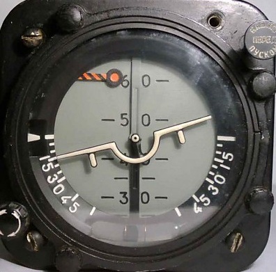
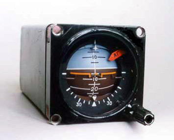
24. Artificial Horizons Tumble at extreme angles and become useless.Except the Russians have had an artificial horizon that does not tumble all along! but we don't want it because it is Russian!
It seems to be poorly publicized information that the instrument that is supposed to keep you under control in the clouds stops working at precisely the moment that you need it most, at that moment you are supposed to realize this occurring and switch to the turn and bank indicator and indirect cues and rote recovery schemes. Good Luck! Variations in the angle and propensity to tumble varies across models and has never been disclosed to me. The simple rate gyro of the turn and bank indicator apparently does not tumble. Apparently the Russians use an artificial horizon display that spits the two axis of mechanical artificial horizon display into two separate components, this display apparently does not tumble. There is some evidence that it is also more intuitive to first users. The horizontal is like a separate turn indicator which tilts relative to the instrument NOT to relative to the panel. So it is like you are flying the the airplane in a separate world by remote control. The The Russians have rotten weather and maybe know what they are doing. Our Type of Artificial Horizons are apparently have become standard though horrible and likely a cause of much death. I do not know if the new electronic displays tumble or not, I do know they fail for lack of electricity and other reasons. In particular engine failure is a threat to aircraft systems. For myself I would like a wind driven venturi artificial horizon of the non tumbling type. Here are some photographs of Russian types. Some of the Russian types have inverted coloring to our expectations.The model number of the newer on seems to be AGB-3. I have not found a source although US YAK operators do have them. Presumably India,China and Russia would be potential sources. If they are not certified in the US for non experimentals, They could be placed next to a certified unit of the other display tumbling certified type.
25. Instrument (Blind) landing systems antenna project a glide path for the plane to land at on the runway... but … the antennas also project a more incorrect beams above and below the correct beams which will guide the plane to an unaturally steep or flat glide that will probably confuse the pilots into not bieng able to maintain on the beam and hopefully go around or in some cases crashing into the ground. Autopilot systems that attempt to help the pilot by extrapolating a from a lost signal may guide the plane into the ground base on a brief exposure to the wrong signal.